|
n System composition
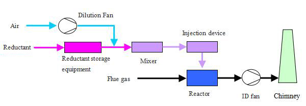
Selective catalytic reduction denitrification systems generally consist of a reductant system (including storage, preparation, supply), a catalytic reaction system (Including flue, ammonia dilution, mixing, injection, reactor and other devices), a common system (steam, water, compressed air, etc. ), an electrical control system ,and an online monitoring system.
n Process flow diagram

n Technological process
The flue gas enters the SCR reactor and is evenly mixed with the ammonia (gas) injected from the injection device. The NOx in the flue gas is reduced to N2 and H2O by the catalyst through the catalyst bed in the reactor.
The reductant may be ammonia water, liquid ammonia or urea.
When ammonia is used as the reductant, an ammonia solution with a mass concentration of 20-25% should be used. The mixed gas of ammonia and air should be higher than the condensation temperature of water.
When liquid ammonia is used as the reductant, the liquid ammonia is evaporated by the liquid ammonia evaporator to generate ammonia gas, which is mixed with the dilution air and then enters the injection system.
When urea is used as the reductant, ammonia from urea has two forms: hydrolysis and pyrolysis. In the process of ammonia production by hydrolysis, the product of urea solution through the hydrolysis reactor enters into the buffer tank, and then mixes with the diluent air and enters into the injection system. When ammonia is produced by pyrolysis, the urea solution is decomposed by a thermal decomposing device, and the decomposing products are mixed and cooled by dilute air and then enter the injection system.
n Key Features
1) Denitrification efficiency is higher than selective non-catalytic reduction (SNCR), up to 90%.
2) The operation is stable and the ammonia escape rate is low.
3) Compared with the selective non-catalytic reduction method (SNCR), this technology has a high investment and a large footprint.
|


